

Description
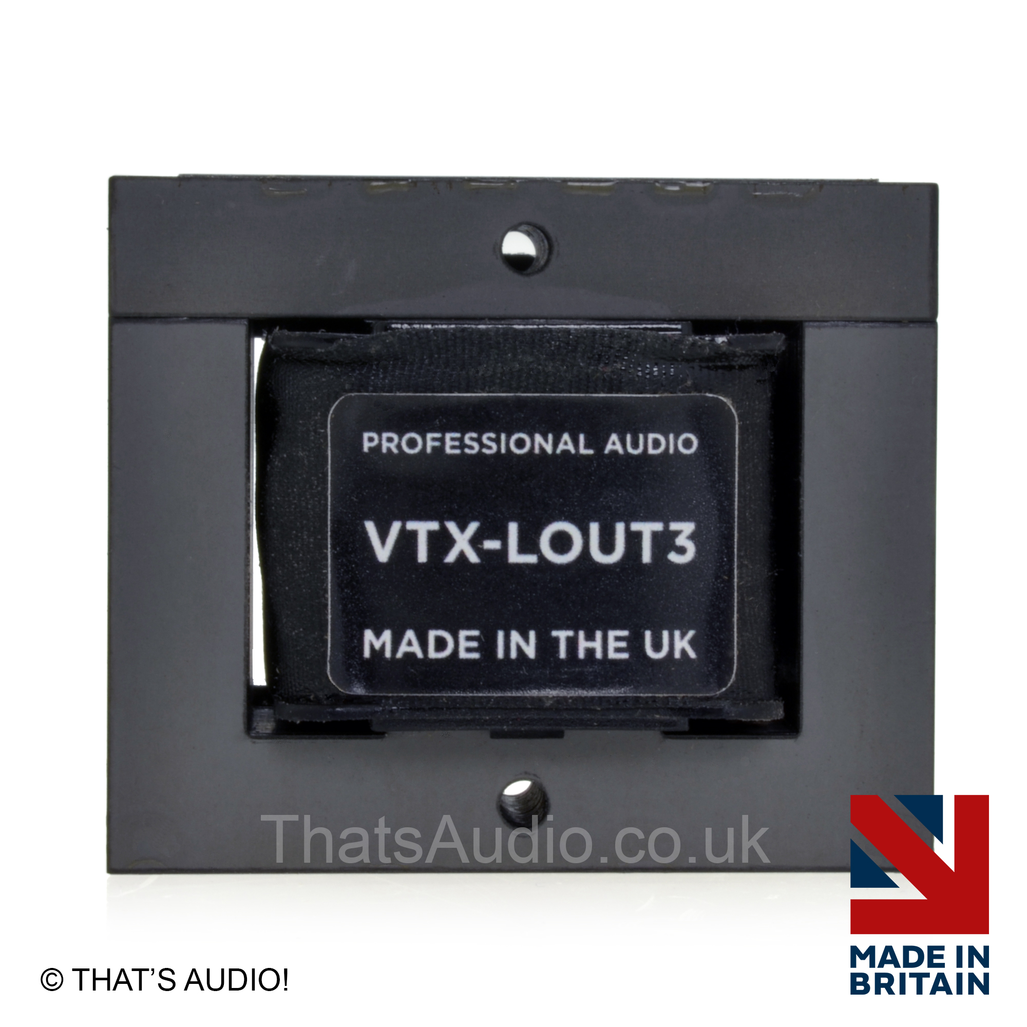
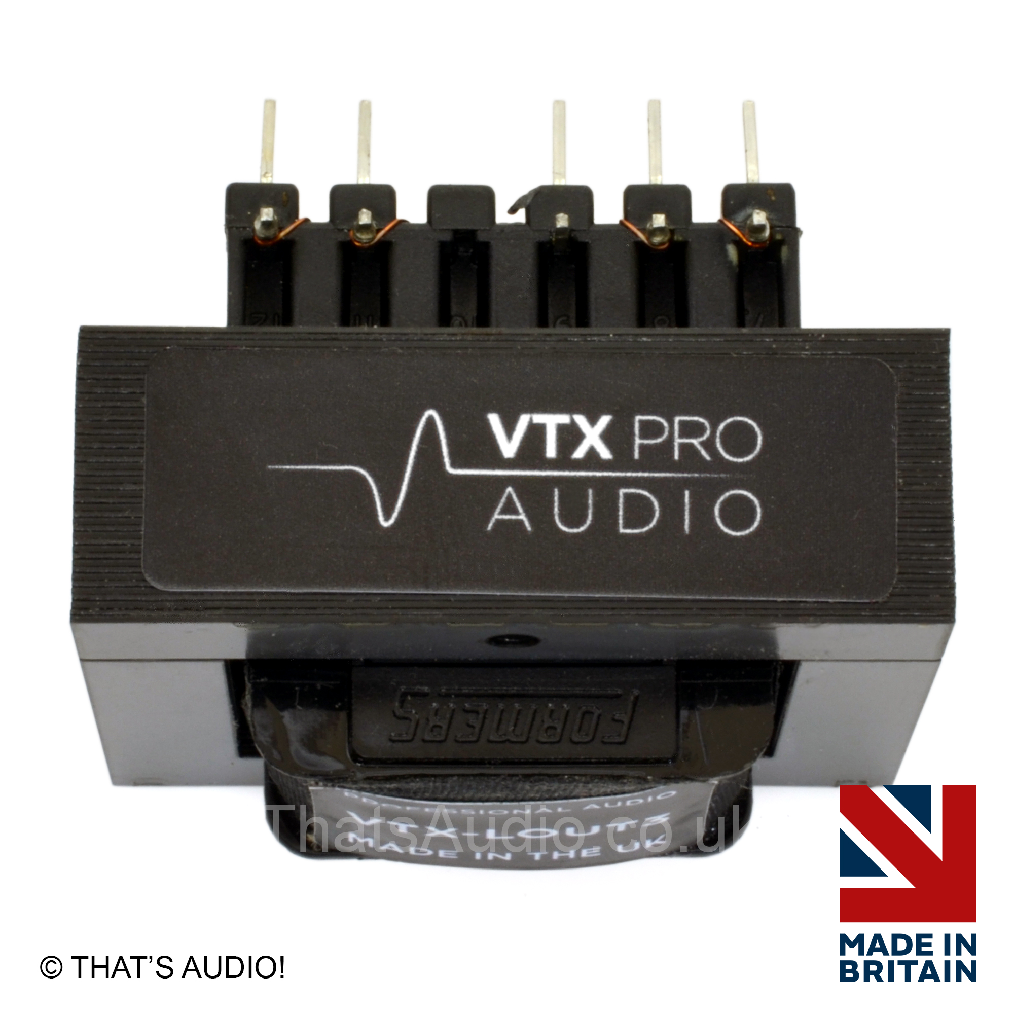
Line Output Transformer VTX-LOUT3
1 : 1: 1 : 1 150kΩ / 600kΩ 24dBu
High performance Line Input Transformer VTXLOUT3 – Used in high performance professional audio and hi-fi systems, line output transformers are small passive devices that help different pieces of audio equipment work well together.
- Reduce Hum and Noise:
They pass the audio signal without a direct electrical connection, which helps stop annoying buzzing or humming sounds caused by ground loops. - Help Equipment Communicate Properly:
They adjust the signal so the output of one device matches the input of another, helping the sound stay clear and strong. - Improve Sound Over Long Cables:
They can connect different types of audio wiring (balanced and unbalanced) and help reduce interference and noise, especially when cables are long.
Transformer Data Sheet – Click to open and DOWNLOAD
- Quadfilar Line Output Transformer
- Can be wired for 1:1, 2:1 or 1:2
- 27dB max. drive level @ 20Hz <1% THD (1 to 1 and 2 to 1 configuration)
- Input impedance (Ω): 687Ω (typ.) @ 1kHz
- Output impedance (Ω): 103Ω (typ.) @ 1kHz (5/6/7/8 S/C)
- Insertion loss: 1.4dB (typ.)
- Leakage inductance @ 1kHz (1 – 11) (5/6/7/8 S/C): 95uH (typ.)
- Interwinding capacitance @ 10kHz, 0.1V:
- Cp-s: 15nF (typ.) (wired 1 to 1)
- Frequency response +/-0.2dB (10Hz – 80kHz)
- Hi-pot, winding to winding: 250VAC
- Grain orientated silicon steel core for maximum level handling
- Operating temperature range: 0 to +70 C
- Storage temperature range: -25 C to +120 C
LINE Input Transformer VTXLOUT3 Electrical characteristics
Specification (test circuit 1):
Turns ratio: 1 to 1 (series wired)
- DC resistance (Ω+/-15%)
- Windings 1+2 (1 – 11) = windings 3+4 (5 – 7): 52.8
- Voltage gain @ 1kHz, -1.89dBu (typ.)
- Maximum input @ 20Hz, <1% THD: 27dBu
Specification (test circuit 2)
Turns ratio: 2 to 1 ( parallel secondaries)
- DC resistance (Ω+/-15%)
- Windings 1+2 (1 – 11): 52.8
- Secondaries (parallel) ((5+6) – (7+8)): 13.2
- Voltage gain @ 1kHz, -8.6dBu (typ.)
- Maximum input @ 20Hz, <1% THD: 27dBu
Specification (test circuit 3)
Turns ratio: 1 to 2 ( parallel primaries)
- DC resistance (Ω+/-15%)
- primaries (parallel) (1+2) – (11+12): 13.2
- Secondary (series) (5 – 7): 52.8
- Voltage gain @ 1kHz, 2.8dBu (typ.)
- Maximum input @ 20Hz, <1% THD: 23dBu


